Home Products Recessed LED Aluminum Profiles

Recessed LED Aluminum Profiles for Integrated Linear Lighting

Flanged, compact, deep and angled sections for cabinet, shelf, wall and ceiling details. Compare the individual drawing and approve a sample before ordering.

Browse All Recessed LED Aluminum Profiles

What Is a Recessed LED Aluminum Profile?

A recessed LED aluminum profile is a housing arranged partly or fully within a prepared groove or coordinated construction detail. It supports compatible LED tape and a matching cover. The visible trim, body and light opening vary by section, so the mounting method must be checked for the selected model.

A flanged channel can cover the edge of a slot, while an angled or asymmetric section changes the relationship between the LED bed and the illuminated surface. A projecting flange alone does not make a channel suitable for plastering over. Confirm the substrate, support and finishing sequence on a section drawing.

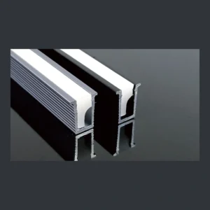
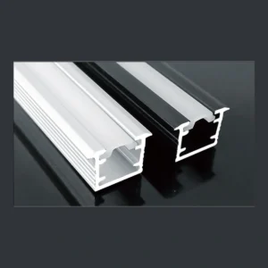
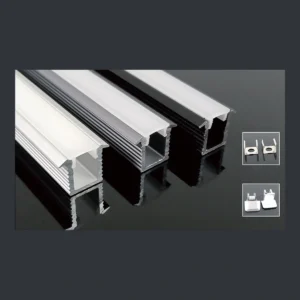
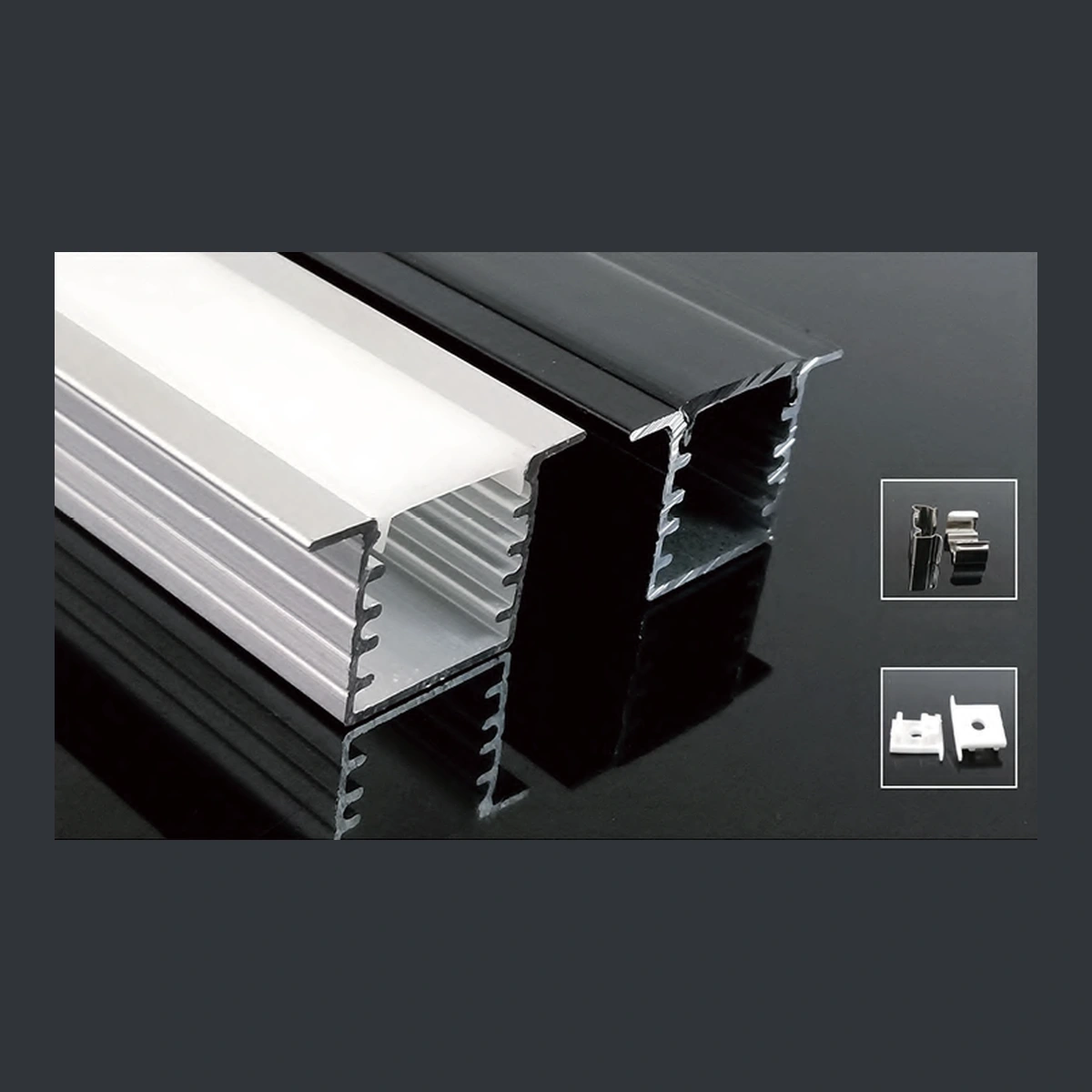
XT-375 recessed LED aluminum profile showing a rectangular channel with internal side ribs and a flanged top with diffuser and catalogue finish examples.

Explore Our Recessed LED Aluminum Profile Collection

Compact & Shallow Recessed Channels

Compare compact and shallow examples such as GD-024, KK-026, SDXT-538 and XT-406.

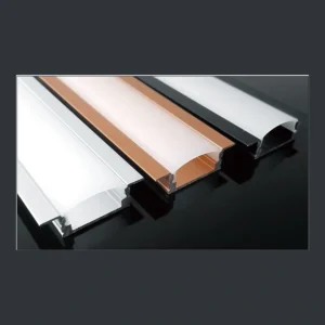
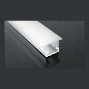
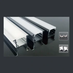
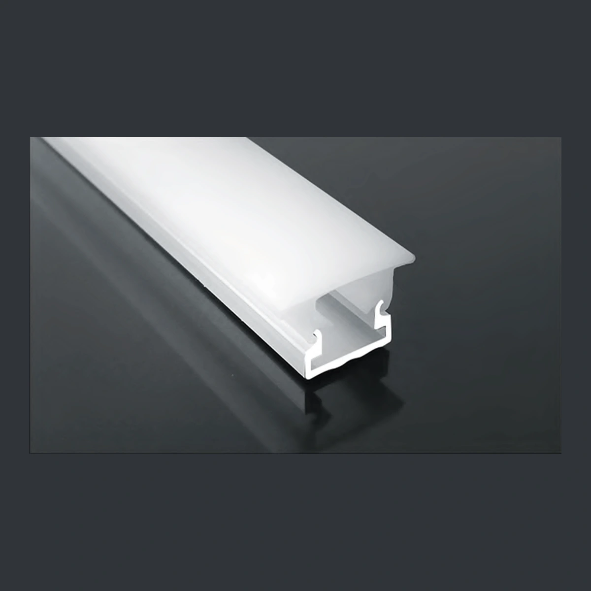
GD-024 recessed LED aluminum profile showing a compact light chamber with shaped upper lips with diffuser and catalogue finish examples.

These outlines suit a short list where available groove space is restricted. Check the real clear tape bed, connector width and optical distance. Do not select a strip by the outside profile width.

Deep & Wide Flanged Profiles

Compare deep or wide examples such as KK-036, SDXT-555, SDXT-558, XT-204 and XT-373.

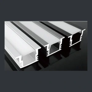
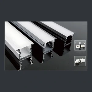
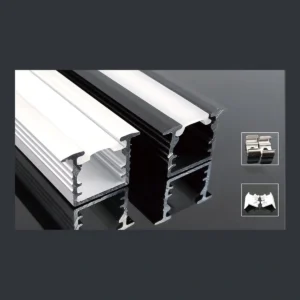
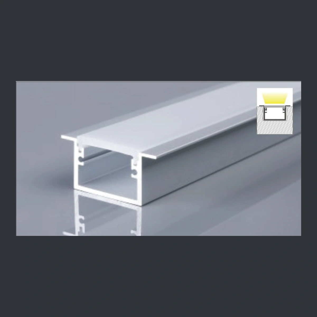
SDXT-558 recessed LED aluminum profile showing a broad top trim over a large rectangular chamber with diffuser and catalogue finish examples.

Review the complete external envelope, including lower structural returns. A wider light chamber or deeper body changes the construction space required, but does not by itself establish a maximum electrical load or a guaranteed dot-free line.

Angled & Asymmetric Light Channels

Compare angled and asymmetric examples such as GD-007, KK-028, SDXT-284, XT-333 and XT-334.

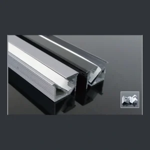
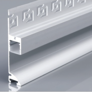
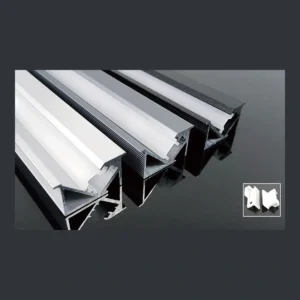
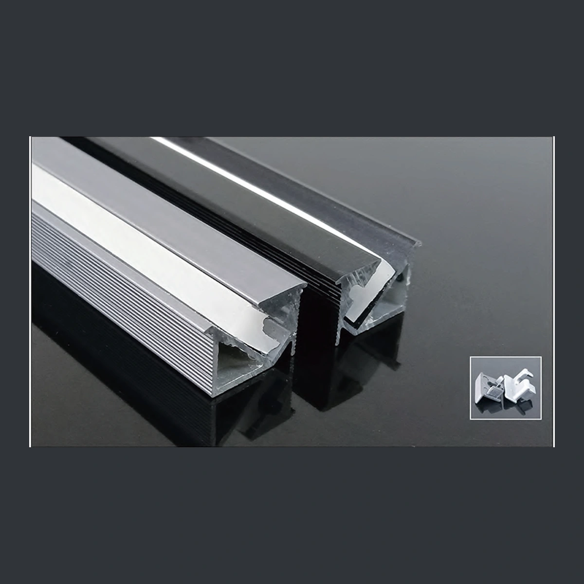
GD-007 recessed LED aluminum profile showing an inclined light bed within a ribbed section with diffuser and catalogue finish examples.

Use the drawing to identify the mounting face and LED bed direction. Test a powered sample at the intended viewing angle. Similar outer dimensions do not establish the same optical direction or fixing method.

How to Choose the Right Recessed LED Aluminum Profile

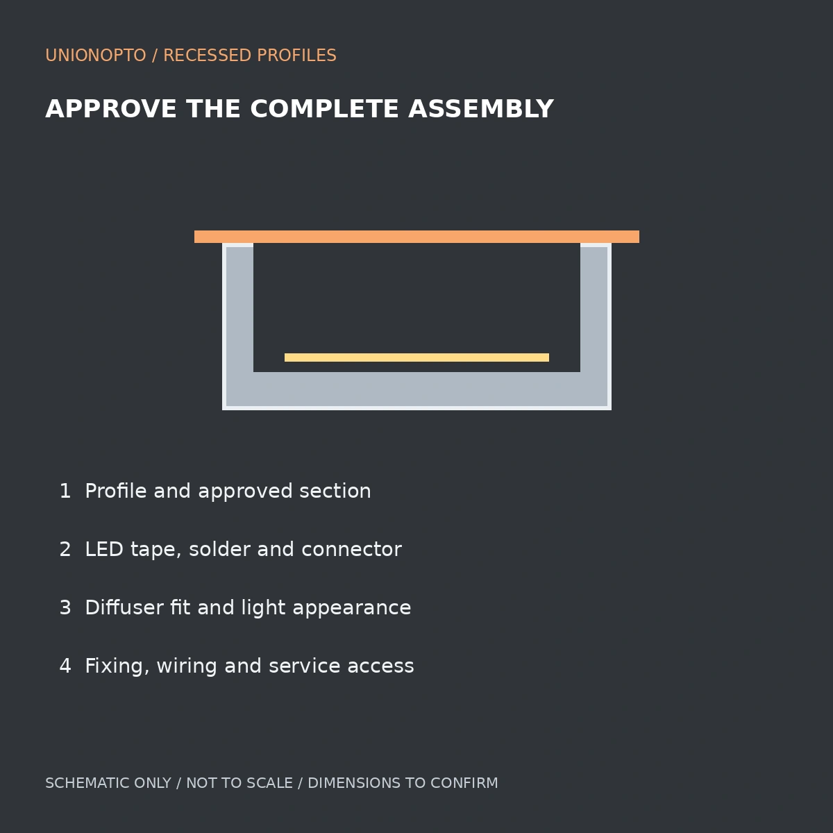
Begin with the construction detail, then compare geometry, tape fit, diffuser and service access. Use the five checks below before approving a housing.

1. Check the External Dimensions

Record total trim width, lower-body width and full external depth separately. Measure the available space in the cabinet, panel or ceiling. 

2. Compare Cross-Section Designs

Compare the tape bed, side ribs, cover lock, flange, lower pocket and cable exit. The same nominal outside size can conceal different internal clearances. Keep the exact sample and drawing revision together when comparing suppliers.

3. Confirm Flange Coverage and Cut-Out

The upper trim needs a sound landing surface. A slot that is too narrow can distort the housing; an excessive opening can leave too little support. Confirm groove dimensions and flange overlap with a real sample. Do not treat total flange width as the groove width.

4. Check LED Strip Compatibility

Include tape PCB, adhesive, solder pads, connectors and any protective jacket in the fit check. Confirm connector height as well as width. Test the actual tape and diffuser together for hot spots and visible diode images.

5. Review Installation and Service Access

Identify how the body is fixed and how the diffuser is removed. Coordinate board thickness, screws or clips, wiring and driver position. Keep a maintenance route available after plastering, painting or cabinetry assembly.

Technical Specifications and Drawing Review

Selection itemInfo.
DimensionW 10~20mm
  
LED tape3~8mm
Surface finishAnodized
Diffuser and finishOpal / Frost/Clear and Black PC cover
AccessoriesEnd caps and mounting clips

Installation Options and Project Pitfalls

Check the Installation Opening

Machine and test one groove before producing a batch of panels. Inspect the fit along the full length. A flange should sit flat without pulling the body out of alignment. Confirm whether the chosen section uses clips, screws, adhesive or a separate mounting accessory.

Plan Joints and End Details

Set out the run, corners, end caps and cable exits before cutting. Allow for the real cutting kerf, finish thickness and joint detail. Check the appearance under illumination. Agree on cut tolerances and end treatments in the order.

Check the Diffuser and LED Strip

A milky-looking cover in a photo does not establish its material or transmission. Request the matching cover specification and an illuminated sample. Evaluate LED density, cover spacing and brightness from normal viewing positions. Record the approved combination.

Allow for Wiring and Maintenance

Leave access to the driver and connections. Ensure cable holes have suitable edge protection and that connectors do not prevent the cover from seating. Review the completed assembly with the installer before closing the construction.

Applications of Recessed LED Aluminum Profiles

Use the following applications to start a drawing review. Suitability depends on the selected section and the complete installation rather than the category name.

Cabinets, Wardrobes and Shelves

Recessed channels can integrate a light line into joinery while protecting the tape from direct handling. Check routing depth against panel strength, avoid concealed connector obstructions and review how the cover can be removed for service.

Wall and Ceiling Grooves

Coordinate construction depth, supporting members, fixing access and finished edges. Distinguish a flanged drop-in detail from a purpose-designed plaster-in system. Do not cover a removable diffuser or unsupported trim with filler.

Retail Stores and Display Cabinets

Use a sample to evaluate reflection, glare and colour appearance on the displayed goods. Angled channels may help direct light, but the actual beam and visual result need review with the specified tape and cover.

Offices, Reception and Hospitality

Coordinate profile joints with ceiling or furniture modules and plan maintenance access. For longer runs, review wiring, driver placement, feed positions and optical consistency as part of the full lighting design.

For wholesalers, lighting manufacturers and project contractors, compare samples and quotations using one agreed configuration.

Send a CAD section, marked-up sketch or physical sample. Unionopto can review existing sections and discuss whether machining or a new extrusion die is needed.

Profile Dimensions and Structure

Specify the usable light bed, mounting body, flange coverage and installation constraints. Highlight the surfaces that must remain visible or removable. Obtain an approved drawing before machining furniture or cutting ceiling openings.

Aluminum Surface Finish

Specify the desired appearance with a sample or agreed reference.Confirm coating thickness allowance, batch colour acceptance and exposed-face protection.

Matching Diffusers and Light Appearance

Confirm cover material, optical finish, retention and removal method. Check supplied lengths and joint appearance. Clear, frosted, opal and other optical options must be confirmed for the actual cover system; no transmission percentage is assumed.

Lengths, Accessories and Drawings

List stock or cut lengths, machining, end caps, clips, joiners, covers and packing. Ask for replacement part availability. Keep the complete model and revision on the sample label and purchase order.

Quality Checks Before Bulk Purchasing

Profile Dimensions and Cross-Section

Check external dimensions, tape bed, wall thickness, weight, straightness and cover interface against the approved sample. Do not substitute a catalogue model number for measured fit. Keep inspection records tied to the order.

Flange Flatness and Sample Installation

Test the body in the intended substrate and inspect flange contact along the run. Excess force can mask an incorrect opening. Verify fastening access and cover removal after the surrounding finish is complete.

Diffuser Fit and Removal

Inspect fit and visual consistency along the full length. Fit and remove a sample cover without damaging its retaining features. Run the intended tape configuration to assess hot spots and thermal behaviour.

Finish, Accessories and Packaging

Check visible surfaces, end caps, fixing parts and shipping protection. Separate finished faces in the carton, support long lengths and label models clearly. Agree on scratch acceptance criteria and a practical incoming inspection sample.

Frequently Asked Questions

No. Confirm body width, trim overlap, groove depth and support separately with an approved section and a sample.

No. Confirm the fixing and finishing method for the chosen section. A flange does not establish a plaster-in installation.

 Check tape, solder, cables and cover clearance together.

No. Test tape pitch, optical distance, diffuser and viewing angle as a complete assembly.

cover, end caps and clips

Request a written quotation for the actual order.

Request a Quote for Recessed LED Aluminum Profiles

Request a sample or quotation for the complete model and installation detail. Include quantity, required lengths, tape dimensions, cover, finish, accessories, destination and delivery needs.

Attach the construction section or a marked-up drawing. Flag unconfirmed dimensions and tell us whether the profile is installed before or after the surrounding finish.

Send Your Project Requirements

Approve The Complete Assembly schematic guide for recessed LED aluminum profile selection; not model-specific and not to scale.
Scroll to Top

Request A Quote

inquiry led aluminum profile