LED Aluminum Profile Quality Inspection Checklist for Buyers
A practical guide to checking dimensions, finish, diffuser fit and packaging, illustrated with an LSH-1513SS sample.
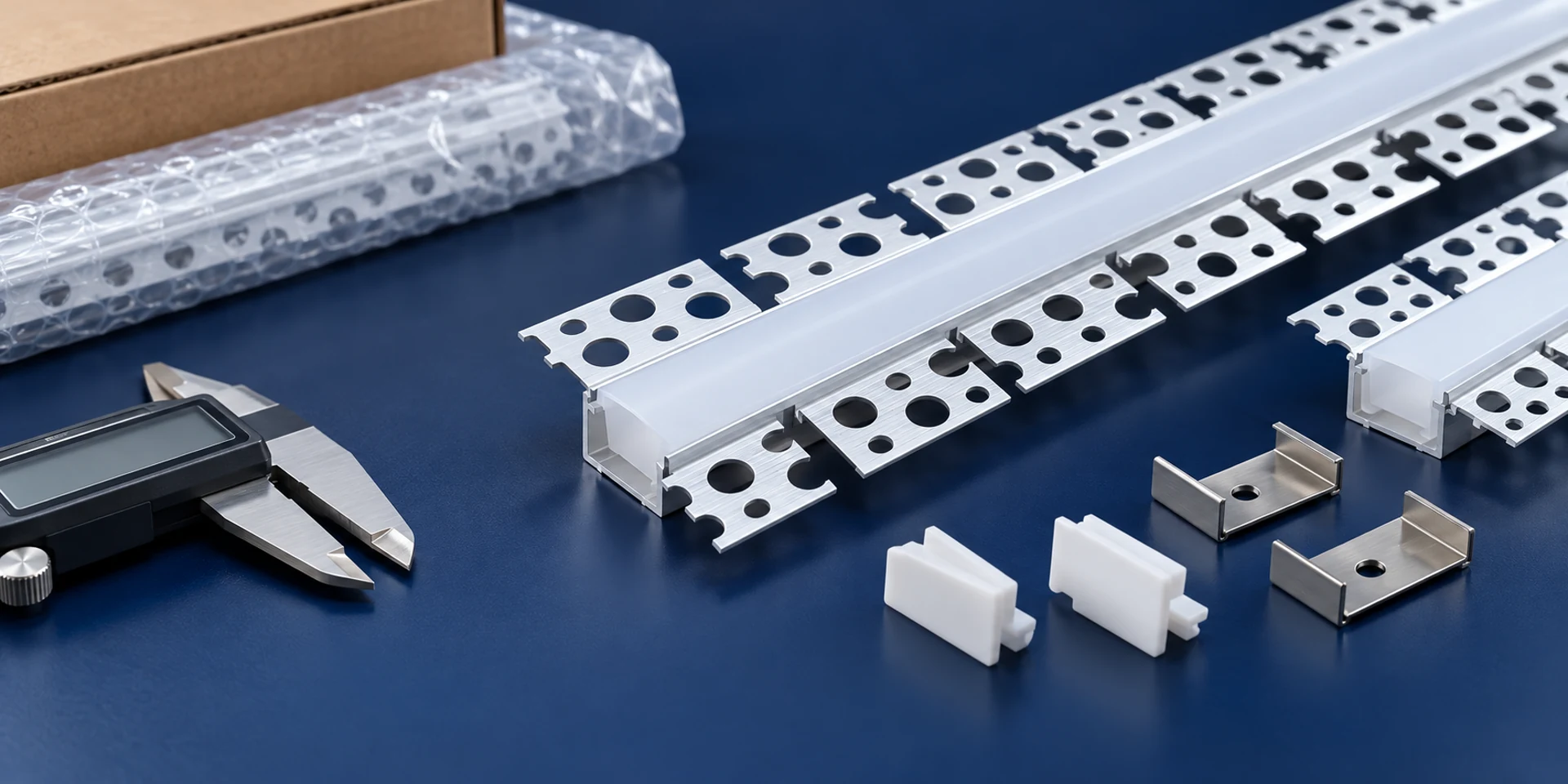
When deciding to place an order or purchase samples, plan a series of quality control checks. Once the samples arrive, or when drawing samples from a production batch, follow the same QC workflow to check dimensions, surface finish, assembly, length and packaging against the order requirements.
This LED aluminum profile quality inspection checklist uses LSH-1513SS drawings and actual inspection photographs to introduce each check, show the results and explain the acceptance requirements. Use the approved sample as the quality reference, and apply the same inspection items and acceptance criteria during production and pre-shipment sampling.
1. Confirm the Drawing and the Actual Profile
Start with the correct model and drawing revision. Confirm the required lengths, finish, diffuser type, accessories and quantities before inspection. Where a dimension or appearance requirement is critical, agree on its acceptance criteria before production.
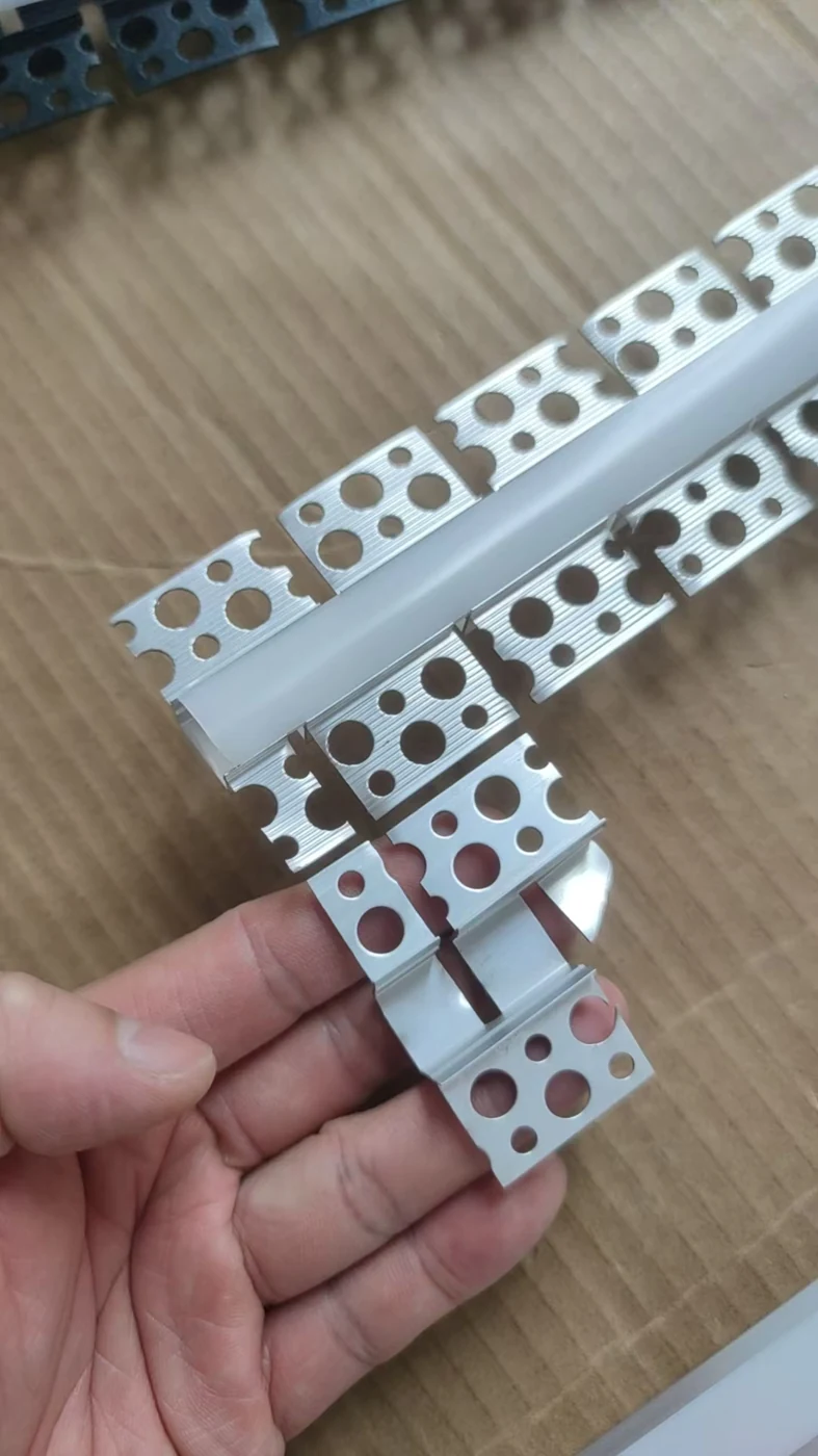
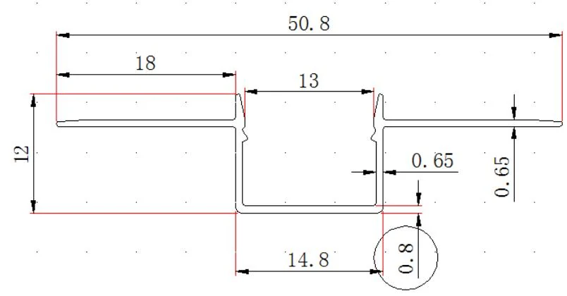
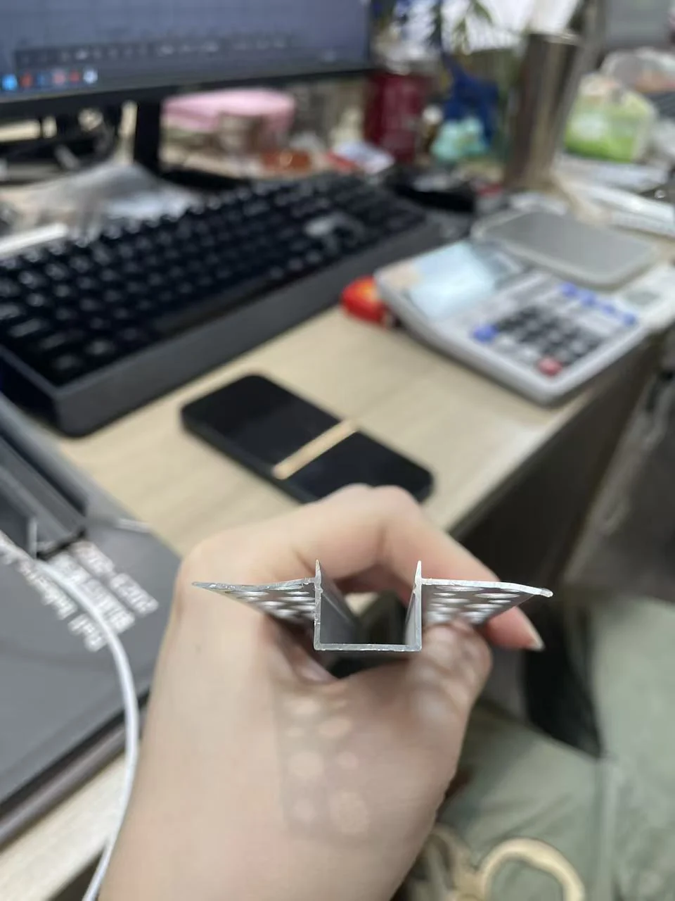
Our LSH-1513SS example pairs a cross-section drawing with photographs of the actual perforated profile and silicone cover. The drawing shows an overall width of 50.8 mm, a channel body outside width of 14.8 mm, an internal dimension of 13 mm and a height of 12 mm. These are different measurements and should not be used interchangeably.
In particular, the 14.8 mm body width is not the internal strip width. Check the cover-retaining geometry and intended strip position when assessing usable space.
Keep the approved sample, drawing and order details consistent. If they differ, clarify which requirement applies before accepting the shipment.
2. Measure Dimensions and Confirm Approval
Measure the dimensions that affect fit and assembly: overall width, channel body width, height, local wall thickness, cut length and any specified holes or slots.
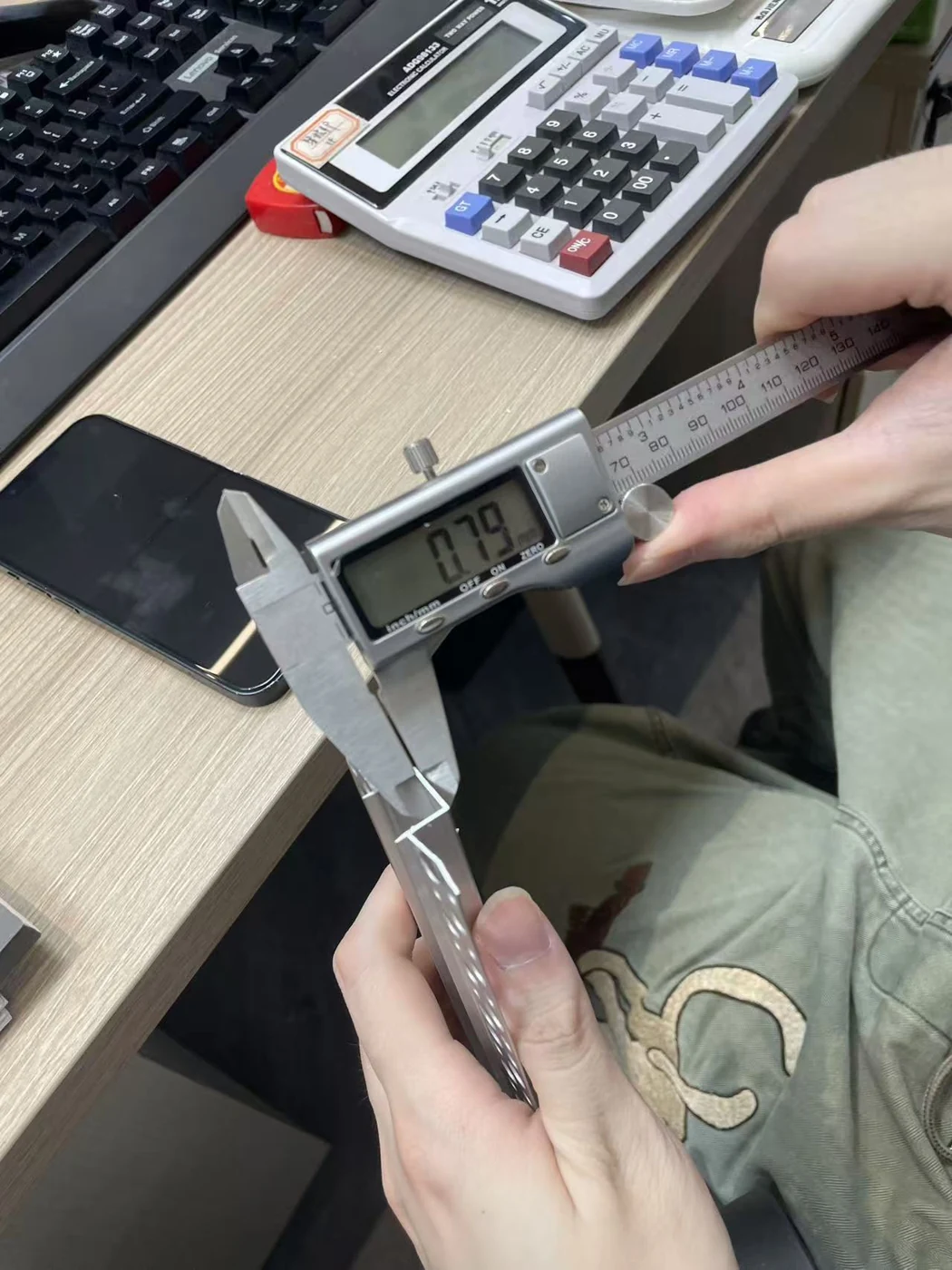
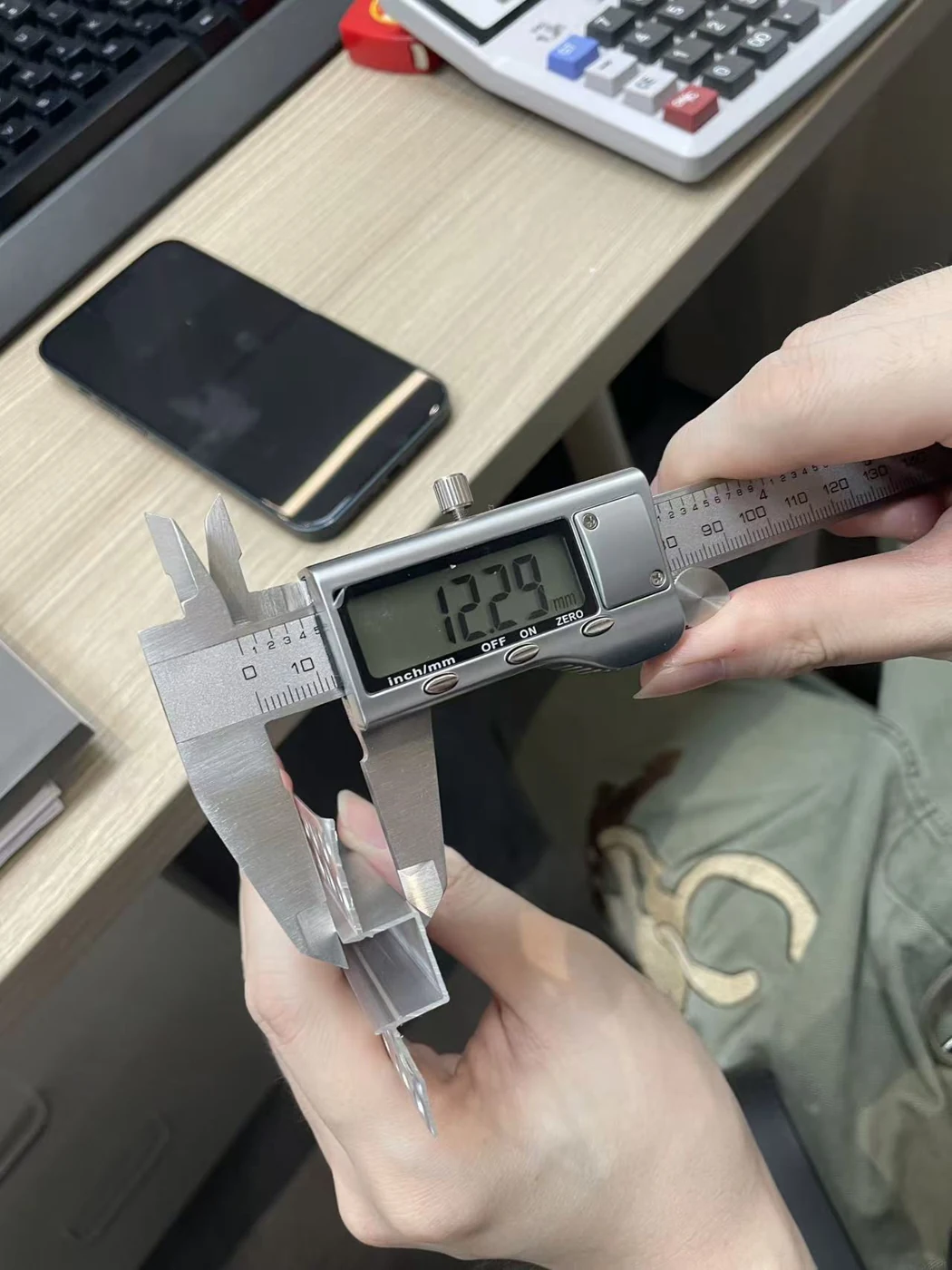
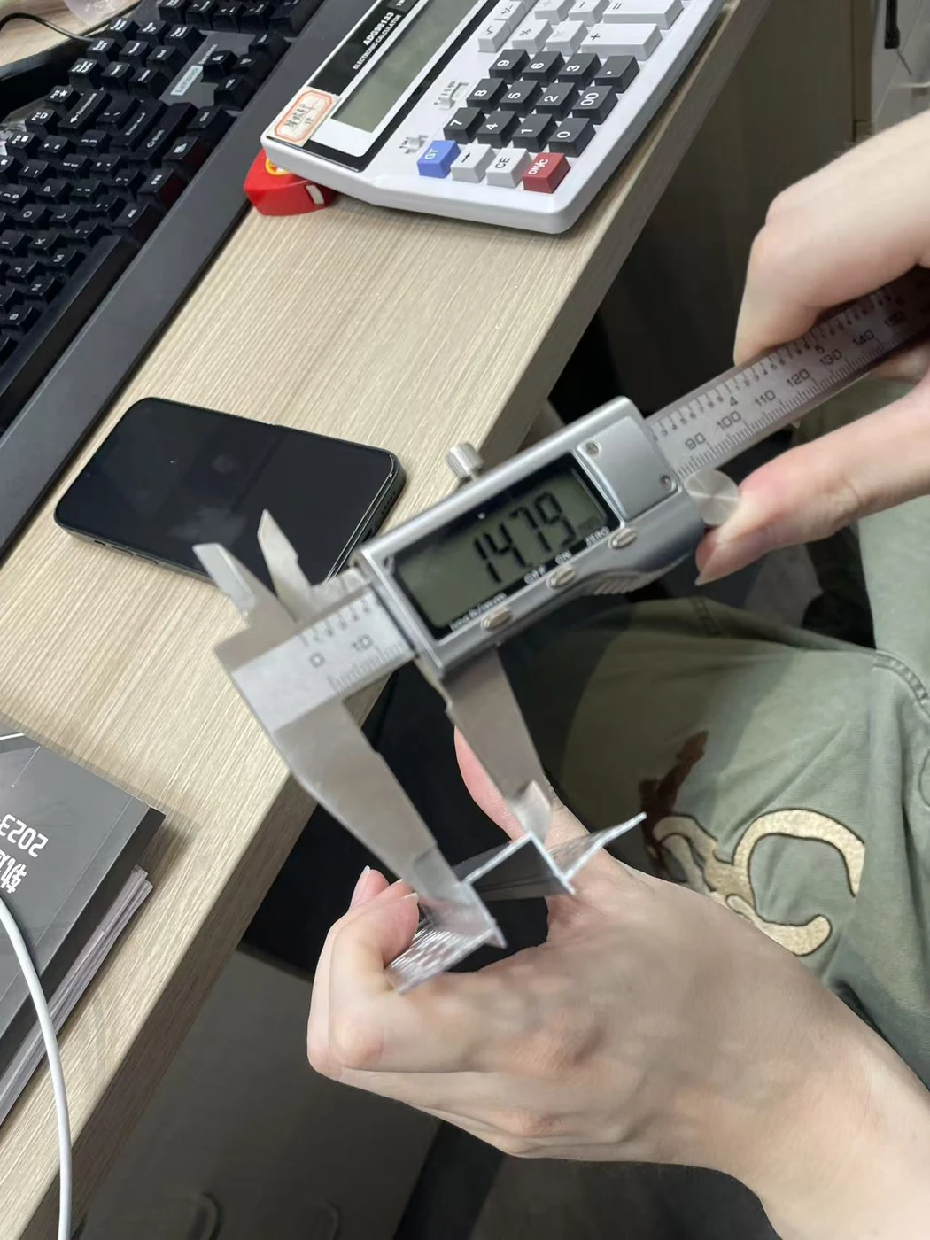
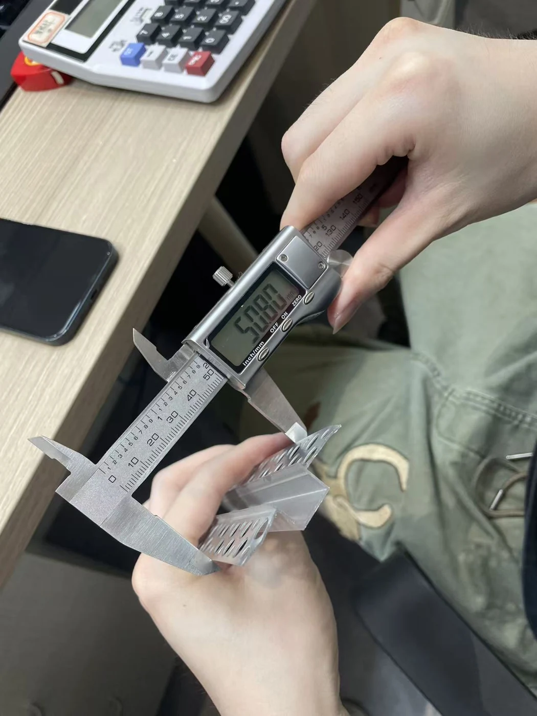
The LSH-1513SS photographs below show the dimensional checks performed with a digital caliper. The measured results are within the agreed acceptance tolerances and are approved. Apply the same measurement points and acceptance criteria when inspecting production samples.
| Measurement | Drawing (mm) | Measured (mm) | Difference (mm) | Approval (Yes/No) |
|---|---|---|---|---|
| Overall width | 50.8 | 50.80 | 0.00 | Yes |
| Body outside width | 14.8 | 14.79 | -0.01 | Yes |
| Height | 12 | 12.29 | +0.29 | Yes |
| Base thickness | 0.8 | 0.79 | -0.01 | Yes |
Difference (mm) means the measured value minus the drawing value. A positive value is above the nominal drawing dimension, a negative value is below it, and 0.00 means the displayed reading matches the nominal dimension to the precision shown. Approval is based on the agreed tolerance, rather than requiring every difference to be zero. All four results in this inspection meet the agreed acceptance requirements, so the Approval column is marked Yes.
Check the caliper zero and measure at the specified points. The overall width measured here is 50.80 mm against the 50.8 mm drawing requirement; this result is within tolerance and is approved. Repeat these checks on the pieces selected for batch inspection.
Measure the base, sidewalls and mounting wings at their specified points. Confirm that each section meets the agreed minimum thickness requirement. Where the actual thickness is above the expected thickness, record this favorable result against the approved specification. The base reading shown here is 0.79 mm for the nominal 0.8 mm requirement and is accepted within the agreed tolerance.
Choosing dimensions before ordering? Read our LED Aluminum Channel Size Guide.
3. Inspect the Surface, Cut Ends and Perforations
Review visible surfaces for scratches, dents, contamination and unexpected color differences. Compare several pieces with the approved finish sample under consistent viewing conditions.
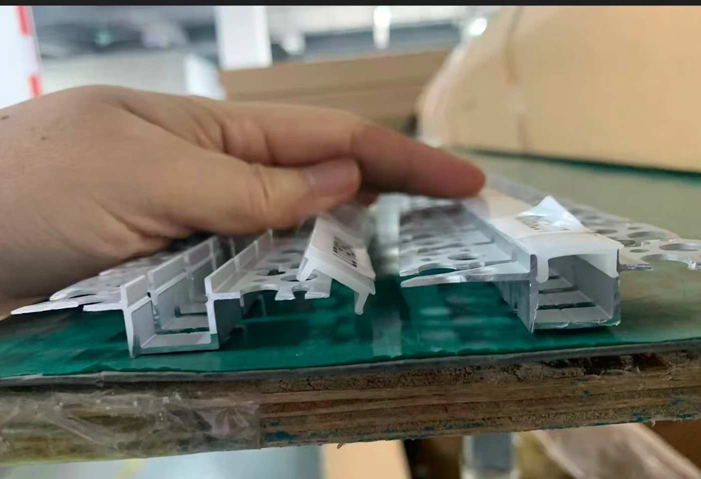
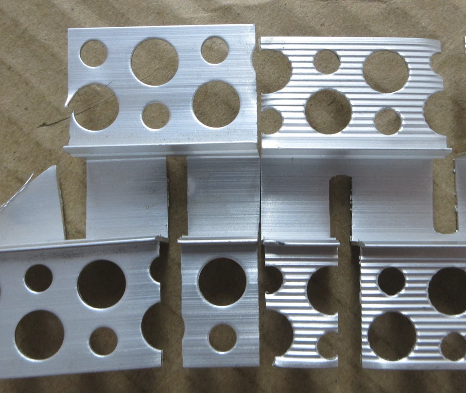
On LSH-1513SS, inspect the channel faces, perforated wings, cover engagement edges and cut ends. Look around openings and trimmed edges for roughness or damage that could affect handling or assembly.
Inspect exposed surfaces under consistent lighting and compare the finish with the approved sample. Check for visible scratches, dents, color differences and rough edges, and separate any pieces that do not meet the agreed appearance requirements.
The inspected sample has acceptable cut edges and no problematic burrs in the areas checked. Use this sample as the workmanship standard for the production batch: inspect the channel faces, perforations and cut ends, remove burrs where necessary, and ensure that every surface meets the agreed finish and handling requirements.
4. Trial-Fit the Silicone Cover and Accessories
Check the profile as an assembly. For this example, review the silicone cover together with the aluminum retaining geometry, then check the specified end caps and mounting accessories.
Install the cover using the intended method. Check that it seats correctly along the tested length, without unexpected lifting, looseness or interference. Include the actual LED strip, connector and wiring when compatibility is part of the order.
Confirm that end caps match the profile and cover combination. Check their fixing method and cable exit. Trial-fit mounting accessories rather than assuming that parts packed together are compatible.
The end-cap image below is a product illustration. Use an actual fitting trial to verify the supplied parts.
If light appearance matters, review a working sample using the intended strip and cover. Mechanical fit does not establish a dot-free result, light output or an IP rating.
For cover and structural options, explore our custom LED aluminum profile solutions.

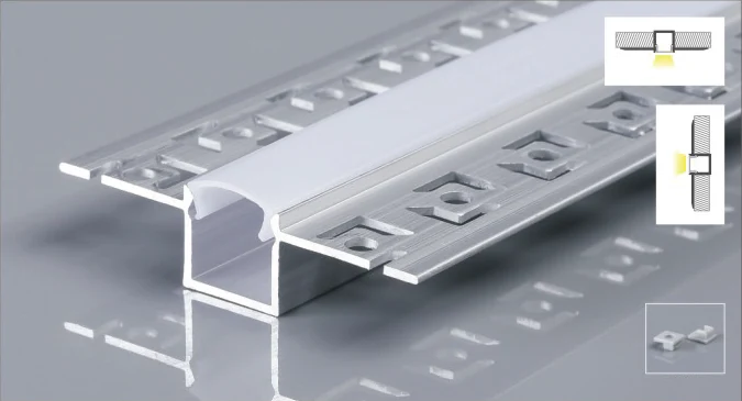
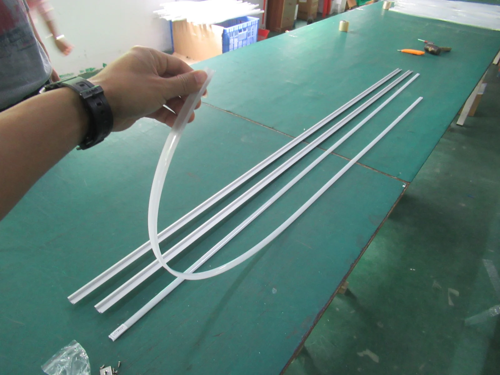
Compare the end caps, mounting clips and screws with the agreed accessory list. Trial-fit the diffuser along the profile and inspect retention, seating and the end-cap fit before packing.
5. Check Length, Straightness and Installation Fit
Establish a clear reference for cut length. State whether the specified length refers to the aluminum body alone or the complete assembly with end caps.
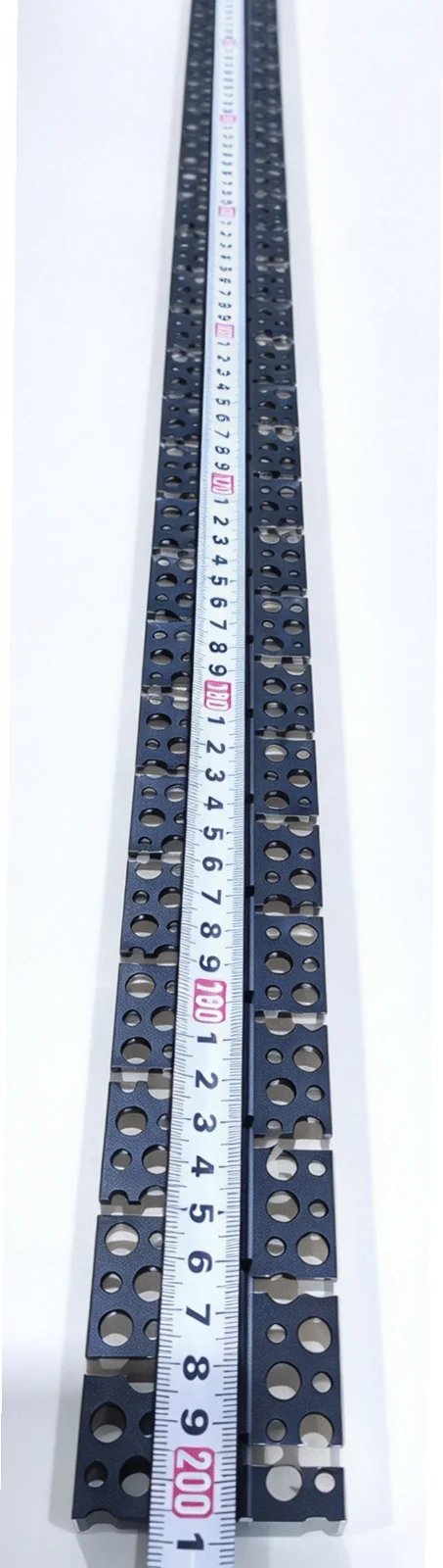
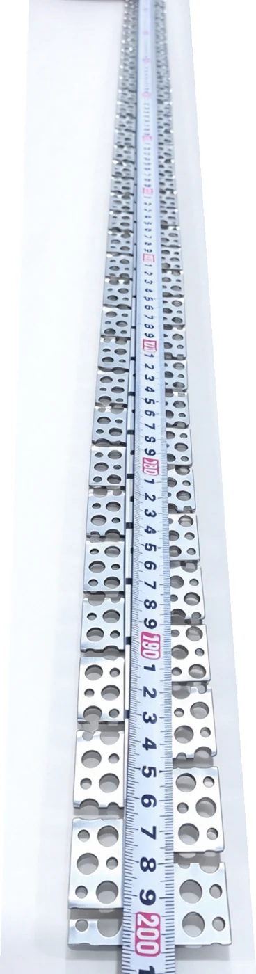
The tape-measure photographs show the actual 2-meter profile length, matching the customer’s 2-meter order requirement. Check the cut length against 2,000 mm and the agreed cutting tolerance, and confirm that all pieces supplied for this order use the specified length.
For straightness inspection, place the 2-meter profile on a flat, supported inspection surface and check for bowing and twisting along its length. Use a straightedge and feeler gauge to measure any gap, then compare the result with the agreed straightness limit. Arrange several profiles side by side to check alignment, and trial-fit adjoining sections to confirm that they join smoothly.
Where sections will join, trial-fit their interfaces and check visible alignment. For a bendable profile, assess the required shape and permitted bending conditions separately; intentional flexibility is different from an unintended defect.
6. Verify Packaging, Accessories and Identification
Confirm quantities in the correct units: pieces, meters, sets and cartons are not interchangeable. Check each model, length and finish against the purchase order and packing list.
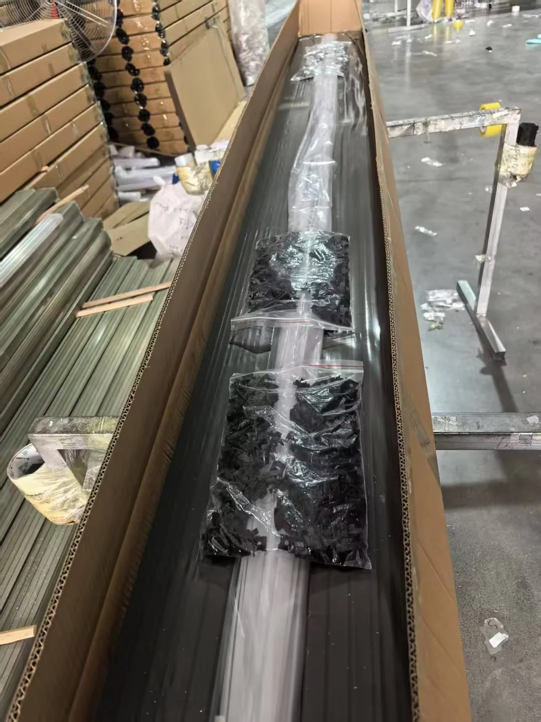
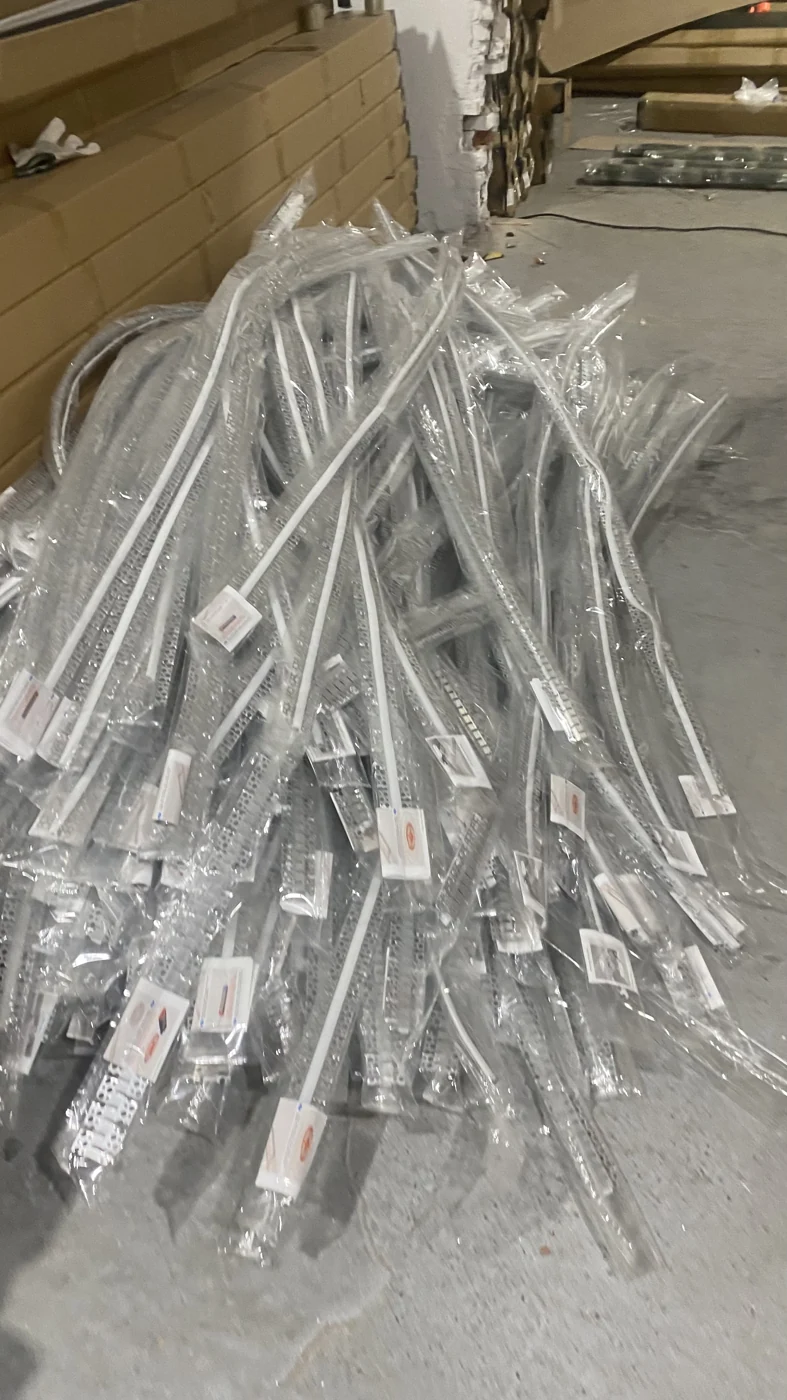
The packing photographs show protective plastic packaging, long cartons and separately packed accessories. Review protection between pieces, support for long sections, end protection and how covers and accessories are kept together.
Check labels for the agreed model, quantity and order identification. Clear identification helps receiving staff avoid mixing similar profiles during storage and assembly.
The packaging shown combines individual PE protection, rigid protective tubes, outer cartons and separately packed accessories. This robust packing arrangement uses additional materials and packing labor to protect the profiles during storage and transport. Before shipment, check that each profile is protected, tube ends are secured, long sections are supported, and the outer carton holds the contents firmly. Keep end caps, clips and screws in a sealed accessory bag, and verify the carton marks against the packing list.
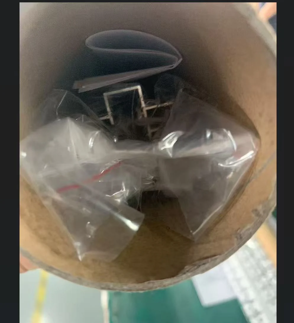

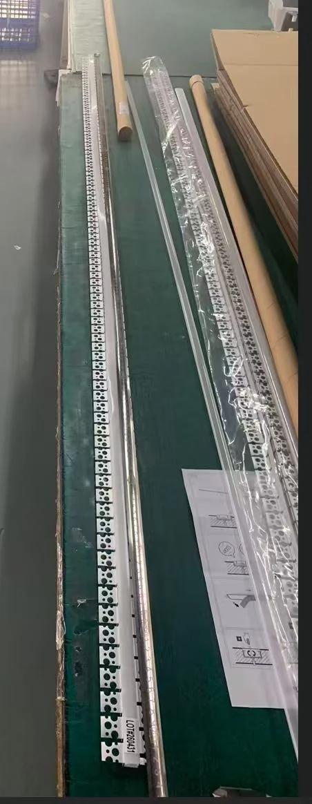

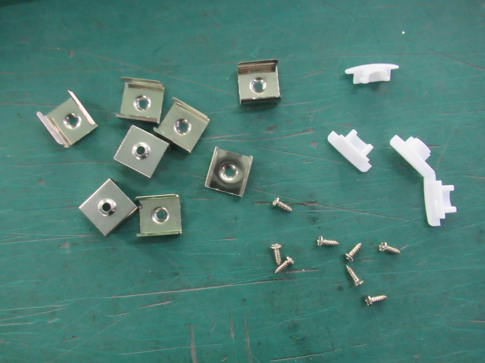
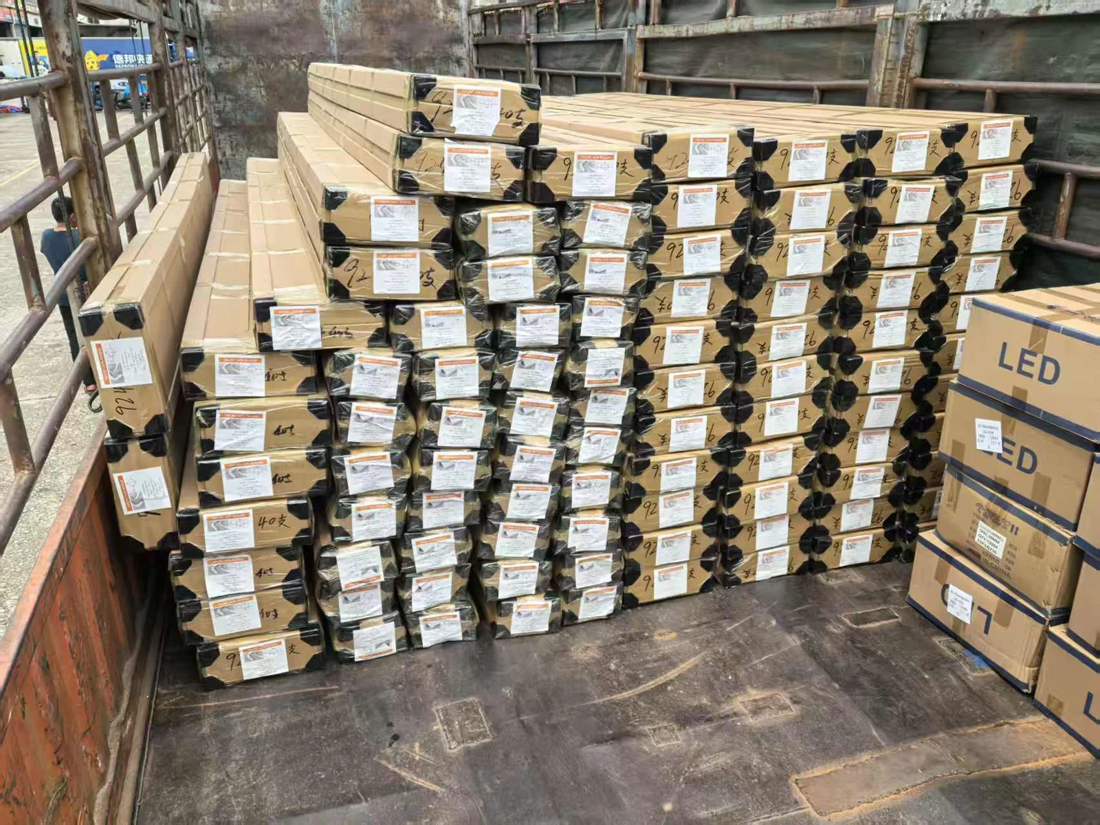

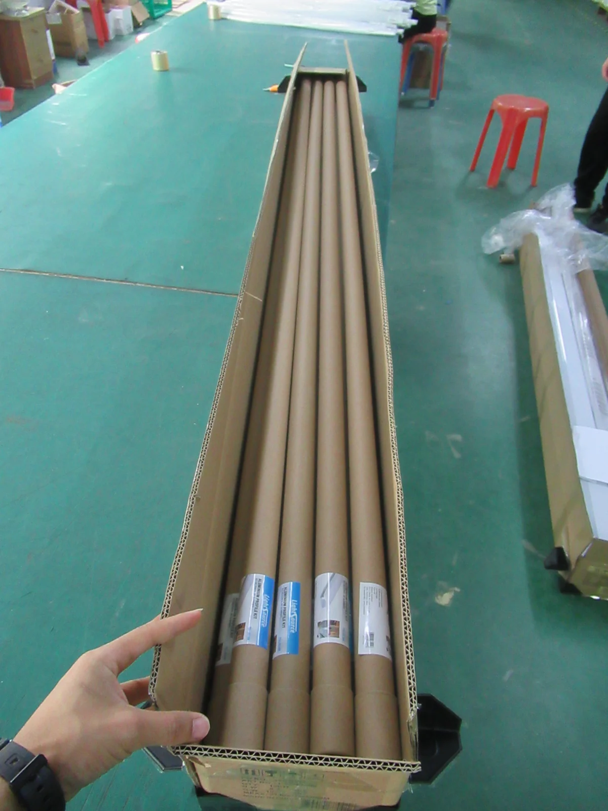
Check individual PE protection, protective tube ends, carton condition and the accessory bag before closure. Match model, length, quantity and carton marks to the packing list. Confirm whether labels are required on individual tubes, bundles or outer cartons.
Frequently Asked Questions
Can the same QC workflow be used for samples and production batches?
Yes. Use the same checks for dimensions, wall thickness, finish, cover and accessory fit, length, straightness and packaging. Approve the sample as the quality reference, then apply those requirements to the pieces selected under the batch sampling plan. Correct any nonconforming items before shipment.
How should wall thickness be approved?
Check each specified wall section against its nominal dimension, minimum thickness and agreed tolerance. A section that meets the minimum requirement is acceptable; thickness above the expected value should be recorded as a favorable result where it meets the approved specification.
How are the dimensional inspection results approved?
Measure the specified dimension, calculate the difference from the drawing value, and compare it with the agreed tolerance. Mark Approval as Yes when the result is acceptable. The four measurements shown in this guide are approved under the agreed acceptance requirements.
Does this checklist cover a complete luminaire?
It focuses on profiles, covers, accessories and packing. Complete luminaires require additional checks appropriate to their electrical, optical and safety requirements.
Discuss Your Inspection Requirements with Unionopto
Send us your profile model or drawing, required lengths, finish, cover, accessories and quantities. Identify the dimensions and appearance requirements that matter to your project so we can review them before order confirmation.
More buying guides: Article Library | Channel Size Guide | Custom Profile Solutions