
Published
How to Diffuse LED Light Strips: Channel Depth, Covers & Dotless Lighting

To diffuse LED light strips into a smoother light line, match the LED strip’s emitter spacing with the distance to the diffuser, choose a compatible cover, and assess the assembled fixture from its intended viewing position.
A smooth line of light starts with the combination of the LED strip, aluminum channel and diffuser. For a visible lighting installation, select these parts together. Consider the spacing between emitters, the available distance below the diffuser and the appearance you want from the finished fixture.
This guide explains how channel depth, emitter spacing and compatible covers work together to reduce visible dots in cabinets, shelves, walls and architectural linear lighting. For a comparison of cover materials and transmission, read our LED channel diffuser cover guide.
How to Diffuse LED Light Strips and Reduce Visible Dots
Separate SMD emitters create bright points along a strip. A diffuser scatters their light, while the space above the emitters gives adjacent beams room to overlap. Closely spaced emitters make this blending easier. A small gap between the emitters and cover can leave the individual light points visible.
Inspect both the illuminated cover and nearby reflective surfaces. A glossy countertop or display panel can make a repeated pattern noticeable even when the fixture itself is outside the normal viewing direction.
Compare LED Spacing Before Selecting a Profile
For a uniformly spaced, single-row SMD strip, approximate emitter pitch is calculated by dividing 1,000 mm by the number of LEDs per meter.
| SMD density | Approximate pitch |
|---|---|
| 60 LEDs/m | 16.7 mm |
| 120 LEDs/m | 8.3 mm |
| 240 LEDs/m | 4.2 mm |
Use the actual emitter layout when reviewing multi-row or alternating-color strips. Compare PCB width, power per meter and light output alongside density. These details help narrow down a compatible channel and strip combination.
Check the Distance from the Emitters to the Diffuser
Read the profile cross section with the assembled lighting system in mind. The overall profile height includes the aluminum base, strip assembly and diffuser structure. The optical space is the gap from the emitting surface to the inside of the fitted cover.
Where installation space permits, a deeper optical cavity provides more room for light to blend. Where the recess is shallow, a denser strip or a suitable COB strip is a practical option to evaluate. Compare complete assemblies at the intended viewing distance before choosing an order specification.
Choose a Diffuser for the Required Appearance
A clear cover prioritizes transmission and keeps the strip visible. Diffusing, frosted and opal covers provide different combinations of scattering and transmission. Select a cover that fits the profile and produces the desired appearance with the chosen strip.
Union Opto’s stated reference transmission ranges are 80–95% for clear covers, 75–85% for diffusing covers, and 60–65% for frosted and opal covers. Confirm the specification for the particular cover supplied with your order. Finished fixture output also depends on the strip and the complete optical assembly.
When Should You Consider COB?
COB strips use a continuous-looking emitting surface, making them useful candidates for compact, visible light lines. Check strip width, cutting interval, power requirements and connector space when comparing options. Review joints and ends as part of the layout so the finished run has the continuity your project requires.
Compare Two Union Opto Profile Examples
The original drawings below show how mounting method, usable width and overall height affect a shortlist. Compare these measurements with the complete strip assembly and the space available in the furniture.
| Model | Drawing dimensions | Selection starting point |
|---|---|---|
| GD-015 · Recessed | 22 mm across the flange, 16 mm body width, 12 mm total height, 11 mm internal width | Evaluate strips up to 10 mm wide for a recessed light line, with connector and cable space checked separately. |
| SDXT-268 · Surface mount | 12 mm overall width, 8 mm total height, 8.5 mm internal width | Evaluate a compatible strip up to 8 mm wide where a compact surface-mounted fixture is needed. |
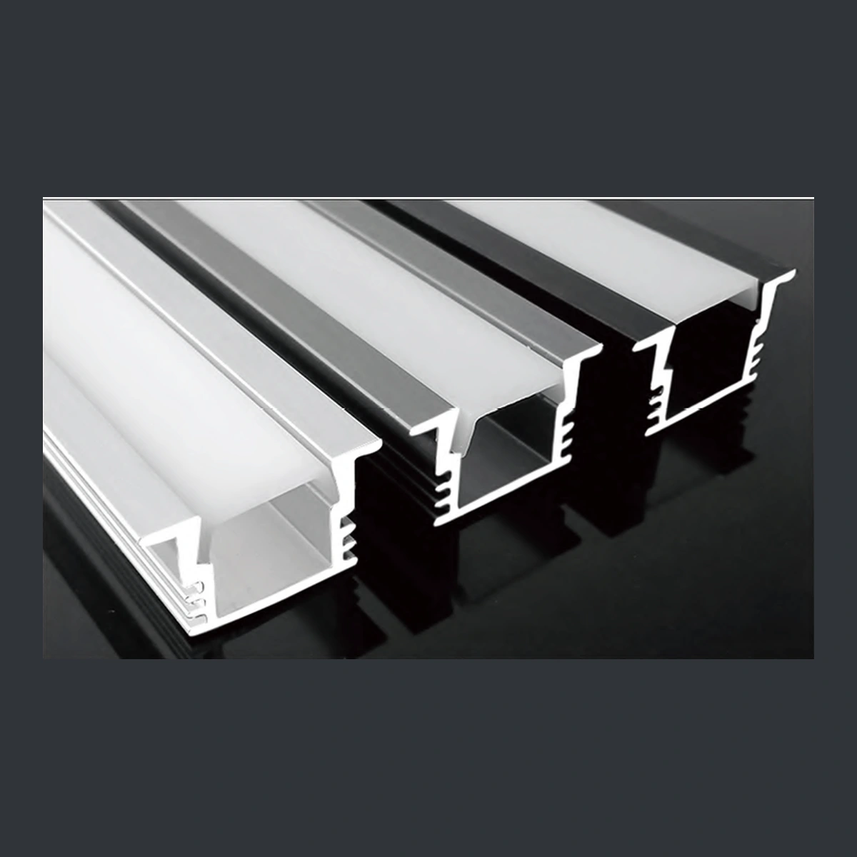
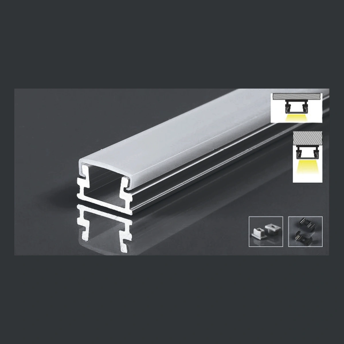
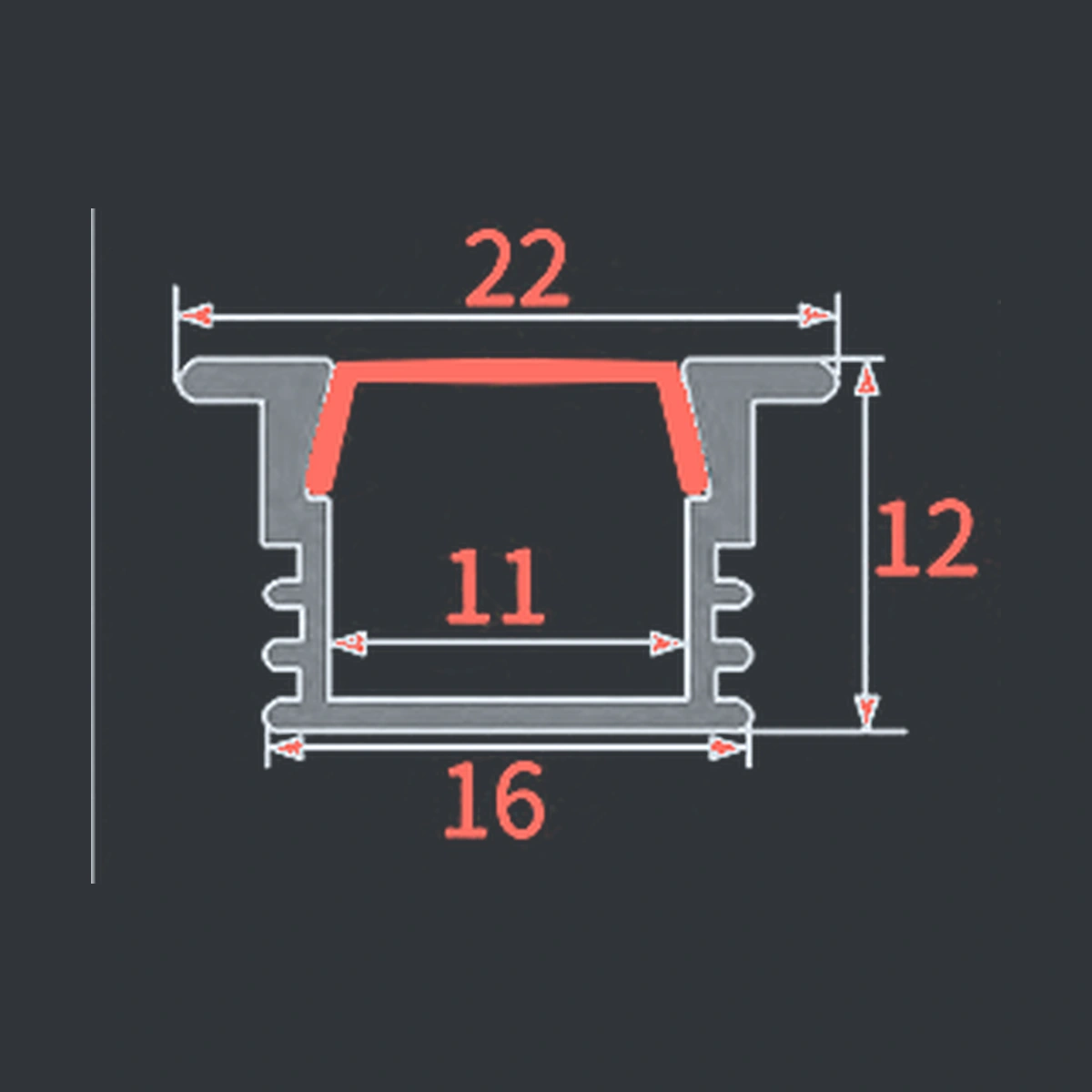
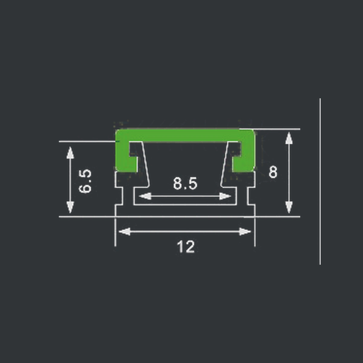
The drawing labels give the profile dimensions. Use the fitted cover and the actual strip assembly to determine the optical gap. For the shallow SDXT-268, a compatible narrow COB strip is a useful starting point for a visible light line. For either model, select the cover and strip together and approve the finished appearance for the project.
Product references · GD-015 recessed LED channel · SDXT-268 surface-mount LED profile
Plan the Mounting Detail Alongside the Light Line
For GD-015, coordinate the routed opening with the profile body, the trim overlap and the remaining panel thickness. For SDXT-268, allow for the supplied fixing method, cable exit and access to the diffuser. Check the finished line from the user’s normal viewing position before repeating the detail across a project.
Related guides · LED aluminum channel size · LED channel diffuser covers · Recessed vs. surface-mount channels
Match the Assembly to the Installation
| Project condition | Starting combination to evaluate | Check before ordering |
|---|---|---|
| Shallow furniture recess | Compatible COB strip or closely spaced SMD emitters with an opal or frosted cover | Usable internal width, strip assembly height and appearance at close range |
| Visible wall or ceiling light line | Profile with room for optical mixing and a cover selected for the required appearance | Direct viewing angles, joints and consistency along the run |
| Glossy kitchen worktop or display shelf | Continuous-looking source with a diffusing cover and carefully chosen position | Reflected image of the light line from normal standing positions |
| Existing low-density SMD strip | Greater optical space where the installation permits, together with a compatible diffuser | Approved sample appearance and delivered light output |
These combinations provide a starting point for sample selection. Specify the approved strip and cover together with the profile when requesting a repeat order.
Fix the Part of the Light Line That Looks Uneven
| What you see | What to inspect | Practical next step |
|---|---|---|
| Regular bright dots along the entire run | Emitter spacing, optical gap and cover | Compare a denser source, more optical space or a different compatible cover |
| Dark interruption at a joint | Distance between emitting sections and connector position | Refine the joint layout and compare cut-to-length samples |
| Light line looks smooth but too dim | Strip output and selected cover | Review the complete fixture output against the project requirement |
| Dots appear mainly on a polished surface | Reflected view of the source | Evaluate the fixture location and source/cover combination from the normal viewing position |
Use a Simple Selection Sequence
- Confirm the mounting method and available installation space.
- Choose a strip width that fits the usable channel interior.
- Compare the strip layout with the available optical depth.
- Select a compatible diffuser and check the required light output.
- Approve a lit assembly under the project’s viewing conditions.
For sample approval, record the profile model, strip specification, cover type, supply voltage, dimming setting and viewing distance. Keep these details with the accepted sample photographs so the same combination can be specified for production.
Frequently Asked Questions
What depth should an LED channel have for dotless lighting?
The required depth depends on emitter spacing and diffuser properties. Select the usable optical gap for the chosen strip and cover. Measure the distance available above the emitting surface and evaluate the selected assembly under the intended viewing conditions.
Can I improve an existing shallow channel?
Start by checking which covers fit the channel. Then compare a denser strip or compatible COB strip within the available width and power specification. A deeper profile is another option where the installation permits it.
Does a COB strip still benefit from an aluminum channel?
A compatible channel provides a defined mounting structure and a finished housing. Choose its cover, end caps and mounting accessories for the installation, and check the strip supplier’s thermal requirements.
Can I choose a cover using transmission percentage alone?
Review its diffusion characteristics and the illuminated assembly as well. Transmission describes how much light passes through a cover, while the visible light pattern depends on the complete combination.
What should I send a supplier?
Send the strip width, type, LEDs per meter where applicable, power per meter, mounting method and available space. Add a reference image of the required lighting appearance and the intended viewing distance.
Find a Profile for Your Light Line
Send Union Opto your strip width, strip type, power per meter, installation dimensions and required appearance. Include the profile length and order quantity so we can help shortlist a compatible assembly.