Published
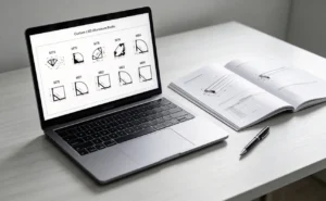
A plaster-in LED channel can be assembled at different stages. Mark the light line, confirm the cutout and fixing points on the profile drawing, and dry-fit a short sample before committing to the full run. Then choose the sequence specified for your system.
Can you fit the LED strip and diffuser before mounting the channel?
Bench assembly is possible when the selected system permits it. Test a short assembled sample in the cutout first. Check that the diffuser and strip leave the fixing points accessible, the lead can pass through the planned exit, and the diffuser can be protected during finishing and removed later. If a screw has to be driven through the inside of the channel, leave that area accessible until the channel is secured. Confirm the sequence with the supplier before using it on a full ceiling run.
- Assemble after finishing. Fix the channel, protect the opening, finish the flanges, then fit the strip and diffuser. See the ALP-3600TL instructions, steps 5–8.
- Assemble after fixing and before finishing. Secure the channel, fit the strip and diffuser, then mask the diffuser before plastering. See the LED-T-RCH4-WT instructions, steps 10–12.
The installation photos in Step 4 show the profile being positioned and the edges being finished on a plasterboard wall mock-up. The LED strip is out of view in that sequence.
Before you start
Have the profile drawing, the actual ceiling board and a short channel sample with its diffuser. Use a double-wing model such as LSH-1513DU for a detail with fixing surfaces on both sides. Review a single-wing model such as LSH-1513SU where the detail has support on one side.
1. Mark the run and cut the opening
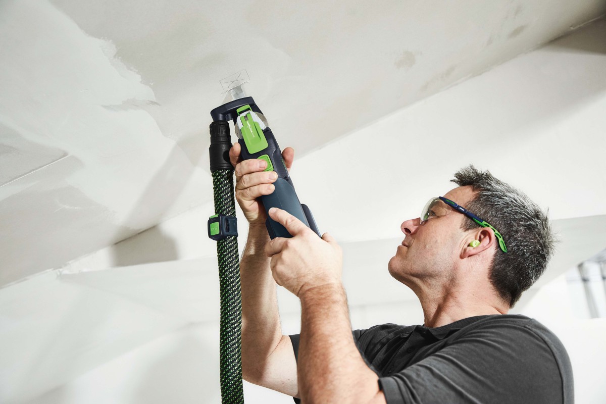
Mark the light line with a laser. Transfer the cutout edges from the selected profile drawing to the board. Check the cavity for framing and services before cutting. For an existing ceiling, locate concealed services and have the installer confirm the cut and support details first.
Before moving on: Check that the cutout clears the channel body and leaves the required support for the flanges.
2. Dry-fit and level the profile

Fit a short length with its diffuser into the opening. Hold a straightedge across the surrounding board and compare the diffuser edge with the planned finished ceiling face. At a joint, align both channel openings before fastening.
Before moving on: The diffuser edge meets the intended finish line and there is no step between adjoining lengths.
3. Fix the channel and confirm the cable exit

Use the fixing points, fasteners and backing specified for the profile and ceiling assembly. Keep fastener heads clear of the diffuser seat and finish plane. Route the lead through the planned exit, and confirm connector clearance and driver access with the electrician before closing the ceiling.
Before moving on: The channel is secure and straight, the lead is accessible, and the cover can still seat.
4. Protect the slot and finish the flanges
Fit the temporary insert or mask specified for your channel. Apply the specified tape and joint compound over the flanges, feathering toward the surrounding board. Keep the diffuser grooves clear while sanding and painting.
Before moving on: The flange disappears into the finish and the protected opening stays clear.
5. Clean the slot and fit the strip and diffuser
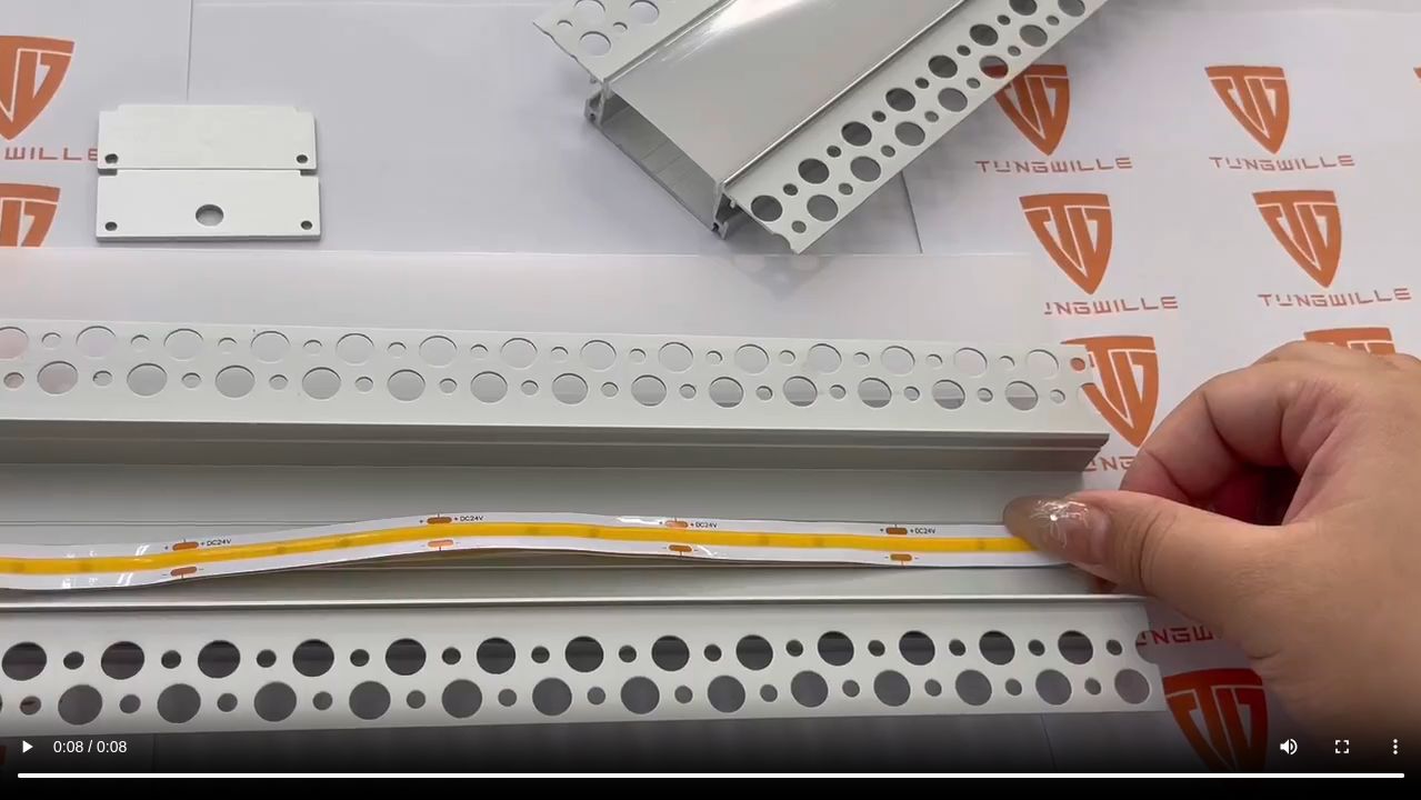
Remove the protection at the stage specified by the supplier. Clear dust and check that the diffuser grooves are open. If the system calls for strip installation after finishing, fit the strip to the clean channel and seat the diffuser using its specified method. For systems assembled earlier, follow their masking and testing sequence.
Before moving on: The diffuser sits evenly and remains removable by the intended service method.

6. Power on and inspect the full line

Have the electrician complete the connection and test. View the lit line from normal positions. If a joint shows a dark gap, check where the strips end, the connector clearance and the location of the diffuser seam.
Before moving on: The line is straight, the joints look even and the driver remains accessible.
Compare the manufacturer installation examples and the trimless channel installation sheet for examples of flange finishing and temporary slot protection.
Request a sample or quote
Send the ceiling section, board thickness, planned light-line length, quantities, diffuser preference and cable exit. Mark the joints, corners and access points on the drawing.
Browse plaster-in profiles · Send your ceiling drawing for review